|
 |
- Best selection for Moderate
clamping force.
- Compact in design.
- Ensures easy component
loading and unloading.
- Appropriate for top clamping
DESCRIPTION:
Vertical Swing Clamps gives high clamping forces.
As low operating pressure, used tn Light duty machining fixtures.
FEATURES:
- Compact design with clamping force.
- Ideally suited where horizontal swing is not allowed
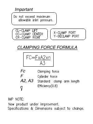
- Min/ Max Operating Pressure 10/70 bar
- Cylirders are available with maniflod mounting as optional
.
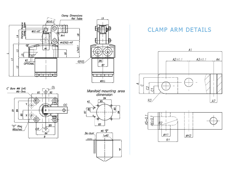
NOTE :
- Refer gereral design notes before selection & use.
- Dimension of depth Should be *P &Ø
decided from dimension-L2
- Ordering specification for seal kit. Add prefix "SK” to the
model number.
- Ordering specification for Marifold cylinider(Example-S35302-M)
- Ordering specification for Port & ManifoId cylinder(Exomple-S35302-MP)
|