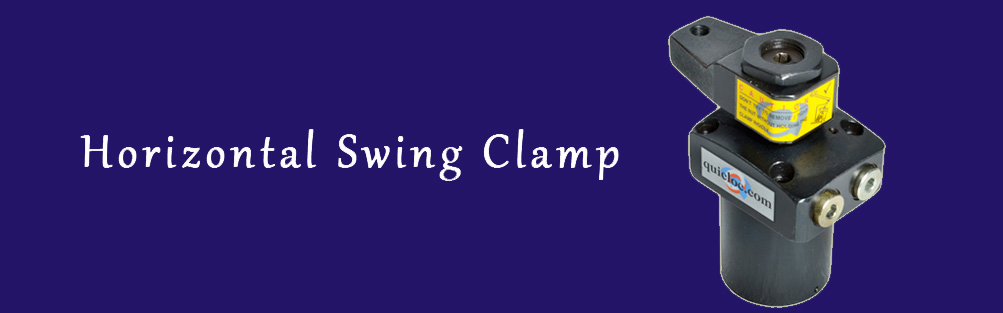
HORIZONTAL SWING CLAMP :

DESCRIPTION:

These Hydraulic Clamping elements are pull type swing cylinders, wherein a part of the total stroke is used to swing the arm (stroke to swing).The shorter part is available as clamping stroke. These swing clamps are having a special feature during the rotation (swing),

FEATURES:
  • Min / Max Operating Pressure 10/70 bar
  • Large clamping range.
  • Double acting ranges.
  • very compoct cylinder design.
  • 360 adjustable arm location.
  • Arm swing will be 90 ±3
NOTE :
  • Refer general design notes before selection & use.
  • Given forces are for the standard arm lever.
  • Pressure ond flow should be reduced if clamp arm length is increased (Refer catalog graph sheet no-Gl)
IMPORTANT:
  • If the system flow rate exceeds, use one way flow control valve in the upstream hydraulic lines.
  • Length of Clamping arm . weight of Clamping arm, max. Permissible flow rate and working pressure are all importan. Refer graphs for arm length and working pressure.
  • Keep weight of Clamping arm to a minimum.
  • Actual clomping tokes place only when the cylinder has completed its 90^0 swing stroke.
  • Clamping allowed only in clamping stroke not in swing stroke.
  • Do not exceed max. flow rate. If flow rates are exceed, swing cylinder indexing mechanism may be permonently domaged.
New product under improvment. Specifications & Dimensions subject to change. .   

  Model No. :C.W S46301 S46303 S46305 S46307 S46309
  Model No. :C.W S46302 S46304 S46306 S46308 S46310
  Force FKN @ 70 bar 1.5 3.2 3.8 6.2 09
  Swing Stroke 6 6 10 10 12
  Clamping Stroke 8 8 10 10 10
  Total Stroke 14 14 20 20 22
  Pistion dia/Rod dia 25/16 36/22 40/25 50/30 60/36
  Oil Volume Clamp cc 4.05 8.93 15.32 25.14 39.82
  Oil Volume deClamp cc 6.8 14.25 25.14 39.28 62.21
  Max Operation Pressure 70 bar
   Min Operation Pressure 10 bar
   Accuracy of 90° swing angle 90+30
  L 103.5 121 145.5 159 175
  L1 64.5 79 89 94 109
  L2 39.5 51 59 63 71
  L3 67.5 82 92.5 98 113
  L4 11 11 12 12 16
  L5 17 17 23.5 24 26
  L6 12 14 18 24 24
  L7 10 11 15 17 16
  L8 05 05 09 09 08
  L9 8.5 9.5 13.5 16 15
  L10 16 17 17 17 21
  Ød 16 22 25 30 36
  Ød 16 22 25 30 36
  Ød-0.1 17 24 28 34 38
  Ød-0.1&0.2 36 48 55 65 75
  B 49 61 69 81 92
  B1 29 35.5 39 46 52
  B2 40 51 60 70 80
  B3 31.4 40 47 55 63
  B4 15.7 20 23.5 27.5 31.5
  B5 31.4 40 47 55 63
  B6 15.7 20 23.5 27.5 31.5
  B7 20 25.5 30 35 40
  B8 16 22 24 30 32
  M1xpitch M12 M18x1.5P M20x1.5P M22x1.5P M30x1.5P
  G-(X2) G1/8" G1/8" G1/8" G1/8" G1/8"
  A/F 18 30 32 40 46
  Ø(X4) 7..5 9 11 11 14
  ØR 4.5 5.5 6.5 6.5 9

CLAMP ARM DETAILS:

  Model No. : S46301 S46303 S46305 S46307 S46309
  Model No. :C.W S46302 S46304 S46306 S46308 S46310
  a 50 70 85 100 100
  b 13 18 21.5 25 25
  c 31 45 55 60 65
  d 26 35 40 46 50
  d1 13 17.5 20 23 25
  e 12 14 16 22 24
  f 17 20 24 32 32
  g 13 15 19 24.5 24.5
  h 26 36 43 50 50
  m M6 M8 M10 M12 M12
  Ød1 16 22 25 30 36
  Ød2 17 24 28 34 38
Specifications subject to improvements.   
 Click here to download a pdf:

  S46301-02 | S46303-04 | S46305-06 | S46307-08  | S46309 -10