 |
|
|
 |
Tie-Rod Long Range Hydraulic Cylinders Quicloc Manufactures Hydraulic Cylinders of Tie Rod Construction:
Tie-rod cylinders are hydraulic cylinders which enable easy dismanteling for repair and servicing. They are usually used for light to medium pressure applications. They are available as long range Tie-rod hydraulic cylinders ranging from 200 to 800mm.
FEATURES:
Dimensions and mounting as per ISO 6020-2 (part 2) Standard*
- Cylinders are ofTie Rod Construction.
- Maximum operating Pressure - 160 bar.
- Cylinder bore25mmto 160mm
- Cylinder barrel made of high stainless steel honed to 0.3 Ra surface finish
- Piston rods are toughned and Chrome plated.
- Piston rods seals are ofMACROTECH(U.S.A.) and PARKER(U.S.A.) make.
- Cushining available for 63 Bore onwards.
- Strokes depend on various factors like mounting, type of loading, column action, over hangs, etc.,
- Please consult us before fixing stroke.
Certain changes to suit the availability of seals are made for some dimensions.
Maximum stroke available
| Bore |
Stroke |
| Ø25 |
200mm |
| Ø32 |
250mm |
| Ø40 |
400mm |
| Ø50 |
500mm |
| Ø63 |
630mm |
| Ø80 |
800mm |
| Ø100 |
800mm |
| Ø125 |
800mm |
| Ø160 |
800mm |
NOTE :
- Ordering specification for seal kit. Add prefix "SK" to
the model Number.
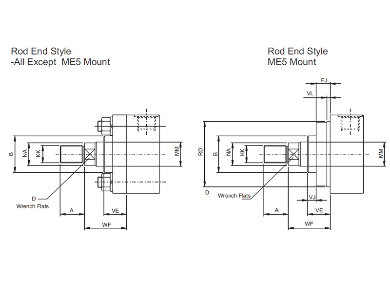
| BoreØ |
MM
RodØ |
KK |
A |
B |
D |
NA |
VE |
WF |
| 25 |
12 |
M10X1.25 |
14 |
24 |
10 |
11 |
15 |
25 |
| 18 |
M14X1.5 |
18 |
30 |
14 |
17 |
15 |
| 32 |
14 |
M12X1.25 |
16 |
26 |
12 |
13 |
22 |
35 |
| 22 |
M16X1.5 |
22 |
34 |
17 |
21 |
22 |
| 40 |
18 |
M14X1.5 |
18 |
30 |
14 |
17 |
16 |
35 |
| 28 |
M20X1.5 |
28 |
42 |
22 |
26 |
20 |
| 50 |
22 |
M16X1.5 |
22 |
34 |
18 |
21 |
21 |
41 |
| 35 |
M27X2 |
36 |
50 |
30 |
33 |
23 |
| 63 |
28 |
M20X1.5 |
28 |
42 |
22 |
26 |
22 |
48 |
| 45 |
M33X2 |
45 |
60 |
36 |
43 |
27 |
| 80 |
35 |
M27X2 |
36 |
50 |
30 |
33 |
25 |
51 |
| 56 |
M42X2 |
56 |
72 |
46 |
54 |
25 |
| 100 |
45 |
M33X2 |
45 |
60 |
36 |
43 |
29 |
57 |
| 70 |
M48X2 |
63 |
88 |
60 |
68 |
27 |
| 125 |
56 |
M42X2 |
56 |
72 |
46 |
54 |
29 |
57 |
| 85 |
M64X3 |
85 |
108 |
70 |
82 |
32 |
| 160 |
70 |
M48X2 |
63 |
88 |
62 |
68 |
32 |
57 |
| 112 |
M80X3 |
95 |
133 |
100 |
108 |
32 |
| VL |
RD
f8 |
VJ |
FJ |
| 3 |
38 |
5 |
10 |
| 3 |
42 |
12 |
10 |
| 3 |
62 |
6 |
10 |
| 10 |
| 4 |
74 |
5 |
16 |
| 7 |
| 4 |
75 |
6 |
16 |
| 88 |
11 |
| 4 |
82 |
5 |
20 |
| 105 |
5 |
| 5 |
92 |
7 |
22 |
| 125 |
5 |
| 5 |
105 |
9 |
22 |
| 150 |
10 |
22 |
| 5 |
125 |
10 |
22 |
| 170 |
7 |
25 |
|
|
|
All dimensions are in millimetres unless otherwise stated..
| Bore |
E |
| mm |
sq.mm |
| 25 |
491 |
| 32 |
804 |
| 40 |
1257 |
| 50 |
1964 |
| 63 |
3118 |
| 80 |
5027 |
| 100 |
7885 |
| 125 |
12272 |
| 160 |
20106 |
| Cylinder push force in kN |
10
bar |
40
bar |
63
bar |
100
bar |
125
bar |
160
bar |
| 0.5 |
2.0 |
3.1 |
4.9 |
6.1 |
10.3 |
| 0.8 |
3.2 |
5.1 |
8.0 |
10.1 |
16.9 |
| 1.3 |
5.0 |
7.9 |
12.6 |
15.7 |
26.4 |
| 2.0 |
7.9 |
12.4 |
19.6 |
24.6 |
41.2 |
| 3.1 |
12.5 |
19.6 |
31.2 |
39.0 |
65.5 |
| 5.0 |
20.1 |
31.7 |
50.3 |
62.8 |
105.6 |
| 7.9 |
31.4 |
49.5 |
78.6 |
98.2 |
165.0 |
| 20.1 |
80.4 |
126.7 |
201..1 |
251.3 |
422.2 |
Piston
RodØ |
Piston
Rod
Area |
| mm |
sq.mm |
| 12 |
113 |
| 14 |
154 |
| 18 |
255 |
| 22 |
380 |
| 28 |
616 |
| 35 |
962 |
| 45 |
1591 |
| 56 |
2463 |
| 70 |
3849 |
| 85 |
5674 |
| 112 |
9852 |
| Reduction force in kN |
10
bar |
40
bar |
63
bar |
100
bar |
125
bar |
160
bar |
| 0.1 |
0.5 |
0.7 |
1.1 |
1.4 |
1.8 |
| 0.2 |
0.6 |
1.0 |
1.5 |
1.9 |
2.5 |
| 0.3 |
1.0 |
1.6 |
2.6 |
3.2 |
4.1 |
| 0.4 |
1.5 |
2.4 |
3.8 |
4.8 |
6.1 |
| 0.6 |
2.5 |
3.9 |
6.2 |
7.7 |
9.9 |
| 1.0 |
3.8 |
6.0 |
9.6 |
12 |
15.4 |
| 1.6 |
6.4 |
10.0 |
15.9 |
19.9 |
25.5 |
| 2.5 |
9.9 |
15.6 |
24.6 |
30.8 |
39.4 |
| 3.8 |
15.4 |
24.2 |
38.5 |
48.1 |
61.6 |
| 5.7 |
22.7 |
35.7 |
56.7 |
70.9 |
90.8 |
| 9.8 |
39.4 |
62.0 |
98.5 |
123.1 |
157.6 |
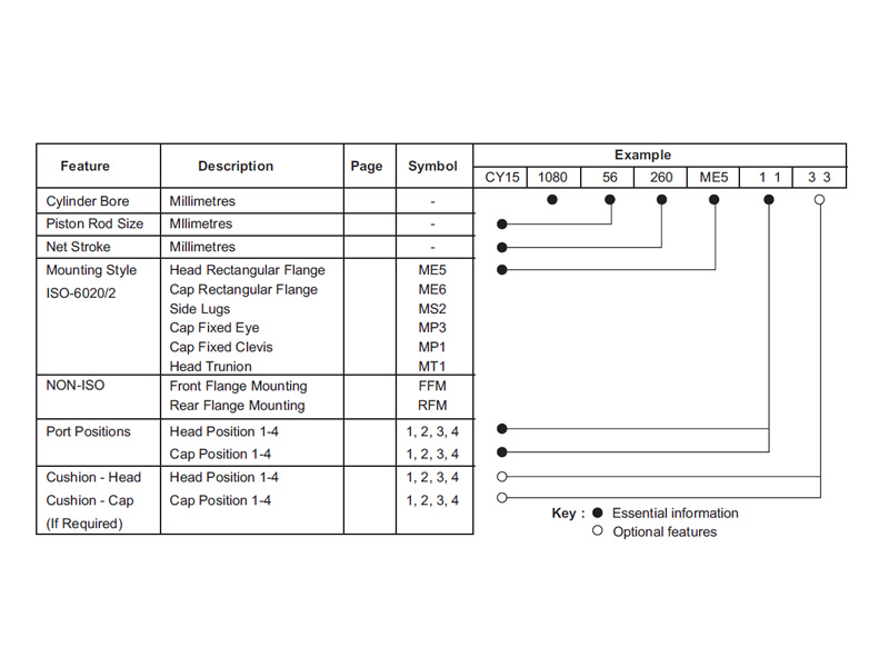
How to Order ISO Tie Rod Cylinders
Each Quicloc series CY15 cylinder is assigned a model number consisting of coded symbols. To develop a model number,
select those symbols represent the cylinder features which you require, and put them down in the sequence indicated by the
example below.
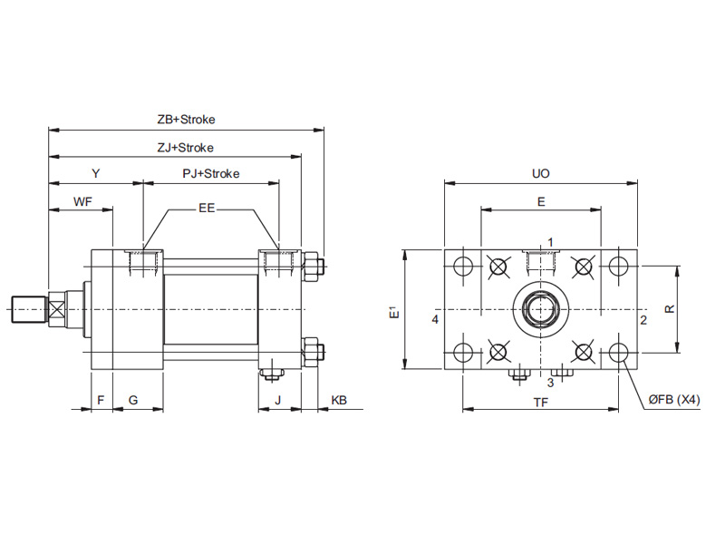
Front Flange Mounting:
Rear Flange Mounting:
Head depth increased by 5mm to accommodate port on 25mm and 32mm bore cylinders..
Pressure not to exceed 70 bar for this type of mounting
Dimensions - FFM, RFM:
| BoreØ |
E |
EE
(BSPP) |
F |
FB |
G |
J |
KB |
R |
TF |
UO |
WF |
Y |
PJ |
ZB |
ZD |
ZJ |
| 25 |
40 |
G¼ |
10 |
5.5 |
35 |
25 |
4 |
27 |
51 |
65 |
25 |
50 |
56 |
125 |
128 |
116 |
| 32 |
45 |
G¼ |
10 |
6.6 |
36 |
25 |
6.5 |
33 |
58 |
70 |
35 |
60 |
60 |
141 |
142 |
132 |
| 40 |
63 |
G¼ |
10 |
11 |
40 |
28 |
8.5 |
41 |
87 |
110 |
35 |
62 |
83 |
173 |
170 |
160 |
| 50 |
75 |
G¼ |
16 |
14 |
42 |
32 |
12.5 |
52 |
105 |
130 |
41 |
67 |
92 |
192 |
191 |
175 |
| 63 |
90 |
G¼ |
16 |
14 |
38 |
32 |
12.5 |
65 |
117 |
145 |
48 |
71 |
102 |
207 |
206 |
190 |
| 80 |
115 |
G¼ |
20 |
18 |
46 |
43 |
16.5 |
83 |
149 |
180 |
51 |
79 |
123 |
246 |
244 |
224 |
| 100 |
130 |
G¼ |
22 |
18 |
15 |
12 |
16.5 |
97 |
162 |
200 |
57 |
82 |
128 |
254 |
254 |
232 |
All dimensions are in millimetres unless otherwise stated.
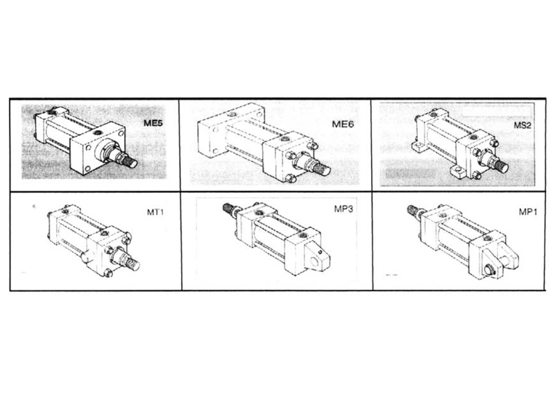
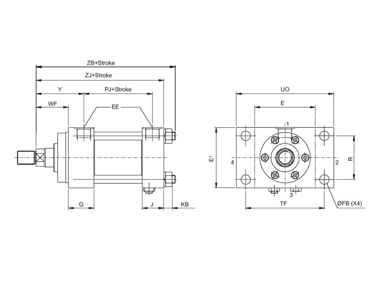
Head Rectangular Flange - ME5
CAP RECTANGULAR FLANGE - ME6:
Head depth increased by 5mm to accommodate port on 25mm and 32mm bore cylinders,
except Mounting ME5 in port positions 2 and 4.
Dimensions - ME5, ME6:
| BoreØ |
E |
EE
(BSPP) |
F |
FB |
G |
J |
KB |
R |
TF |
UO |
WF |
Y |
PJ |
ZB |
ZJ |
| 25 |
40 |
G¼ |
10 |
5.5 |
35 |
25 |
4 |
27 |
51 |
65 |
25 |
50 |
56 |
125 |
116 |
| 32 |
45 |
G¼ |
10 |
6.6 |
36 |
25 |
6.5 |
33 |
58 |
70 |
35 |
60 |
60 |
141 |
132 |
| 40 |
63 |
G¼ |
10 |
11 |
40 |
28 |
8.5 |
41 |
87 |
110 |
35 |
62 |
83 |
173 |
160 |
| 50 |
75 |
G¼ |
16 |
14 |
42 |
32 |
12.5 |
52 |
105 |
130 |
41 |
67 |
92 |
192 |
175 |
| 63 |
90 |
G¼ |
16 |
14 |
38 |
32 |
12.5 |
65 |
117 |
145 |
48 |
71 |
102 |
207 |
190 |
| 80 |
115 |
G¼ |
20 |
18 |
46 |
43 |
16.5 |
83 |
149 |
180 |
51 |
79 |
123 |
246 |
224 |
| 100 |
130 |
G¼ |
22 |
18 |
45 |
42 |
16.5 |
97 |
162 |
200 |
57 |
82 |
128 |
254 |
232 |
| 125 |
165 |
G¼ |
22 |
22 |
58 |
58 |
28 |
126 |
208 |
250 |
57 |
86 |
145 |
292 |
260 |
| 160 |
205 |
G¼ |
25 |
26 |
62 |
58 |
36 |
155 |
253 |
300 |
57 |
96 |
161 |
330 |
286 |
All dimensions are in millimetres unless otherwise stated.
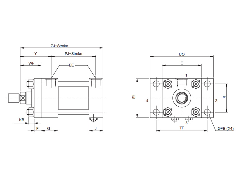
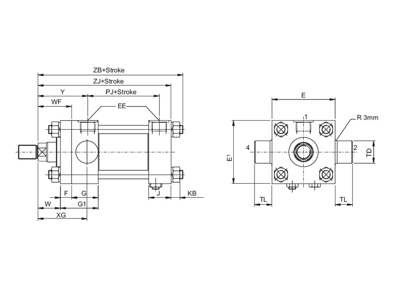
SIDE LUGS - MS2:
HEAD TRUNION - MT1:
Note:
A one-piece head and retainer is used on 125mm and 160 mm bore sizes - G1 dimension on 125 and 160 mm bores, the bolted gland is recessed,
with tie rods screwed into the head
Dimensions - MS2, MT1:
| BoreØ |
E |
EE
(BSPP) |
F |
G |
G1 |
J |
KB |
LH
h10 |
SB |
ST |
SW |
TD
f8 |
TL |
TS |
US |
W |
WF |
XG |
XS |
Y |
PJ |
SS |
ZB |
ZJ |
| 25 |
40 |
G¼ |
10 |
35 |
- |
25 |
4 |
19 |
6.6 |
8.5 |
8 |
12 |
10 |
54 |
72 |
- |
25 |
44 |
33 |
50 |
56 |
77 |
125 |
118 |
| 32 |
45 |
G¼ |
10 |
36 |
- |
25 |
6.5 |
22 |
9 |
12.5 |
10 |
16 |
12 |
63 |
84 |
- |
35 |
54 |
45 |
60 |
60 |
77 |
141 |
132 |
| 40 |
63 |
G¼ |
10 |
40 |
- |
28 |
8.5 |
31.5 |
11 |
12.5 |
- |
20 |
16 |
83 |
103 |
- |
35 |
57 |
45 |
62 |
83 |
98 |
173 |
160 |
| 50 |
75 |
G¼ |
16 |
42 |
- |
32 |
12.5 |
37 |
14 |
19 |
13 |
25 |
20 |
102 |
127 |
- |
41 |
64 |
54 |
67 |
92 |
108 |
192 |
175 |
| 63 |
90 |
G¼ |
16 |
38 |
- |
32 |
12.5 |
44 |
18 |
26 |
17 |
32 |
25 |
124 |
161 |
- |
48 |
67 |
65 |
71 |
102 |
108 |
207 |
190 |
| 80 |
115 |
G¼ |
20 |
46 |
- |
43 |
16.5 |
57 |
18 |
26 |
17 |
36 |
35.5 |
149 |
186 |
- |
51 |
74 |
68 |
79 |
123 |
139 |
246 |
224 |
| 100 |
130 |
G¼ |
22 |
45 |
- |
42 |
16.5 |
63 |
26 |
30 |
- |
40 |
38.5 |
172 |
216 |
- |
57 |
79.5 |
79 |
82 |
128 |
132 |
254 |
232 |
| 125 |
165 |
G¼ |
22 |
58 |
80 |
58 |
28 |
82 |
26 |
32 |
22 |
63 |
50 |
210 |
258 |
35 |
57 |
75 |
79 |
86 |
145 |
159 |
292 |
260 |
| 160 |
205 |
G¼ |
25 |
62 |
87 |
58 |
36 |
102.5 |
33 |
38 |
29 |
80 |
63 |
260 |
318 |
32 |
57 |
75 |
86 |
96 |
161 |
171 |
330 |
286 |
Head depth increased by 5mm to accommodate port on 25mm and 32mm bore cylinders,
except Mounting ME5 in port positions 2 and 4.
All dimensions are in millimetres unless otherwise stated.
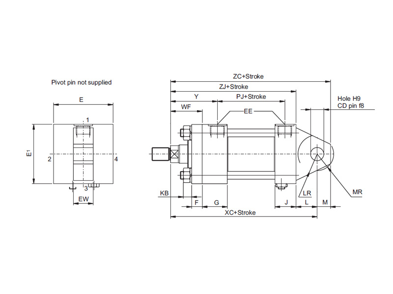
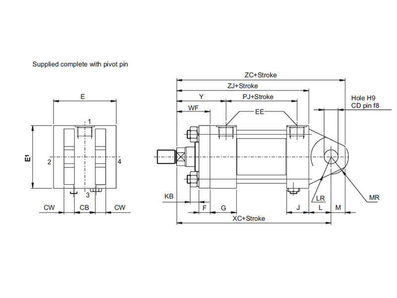
CAP Fixed Eye -MP3:
CAP FIXED CLEVIS - MP1:
Dimensions - MP3, MP1:
| BoreØ |
CB
A16 |
CD
H9 |
CW |
E |
EE
(BSPP) |
EW
h14 |
F |
G |
J |
KB |
L |
LR |
M |
MR |
WF |
Y |
PJ |
XC |
ZC |
ZJ |
| 25 |
12 |
10 |
6 |
40 |
G¼ |
12 |
10 |
35 |
25 |
4 |
13 |
12 |
10 |
12 |
25 |
50 |
56 |
131 |
141 |
118 |
| 32 |
16 |
12 |
8 |
45 |
G¼ |
16 |
10 |
36 |
25 |
6.5 |
19 |
17 |
12 |
15 |
35 |
60 |
60 |
151 |
163 |
132 |
| 40 |
20 |
14 |
10 |
63 |
G¾ |
20 |
10 |
40 |
28 |
8.5 |
19 |
17 |
14 |
16 |
45 |
62 |
83 |
179 |
193 |
160 |
| 50 |
30 |
20 |
15 |
75 |
G½ |
30 |
16 |
42 |
32 |
12.5 |
32 |
29 |
20 |
25 |
41 |
67 |
92 |
207 |
227 |
175 |
| 63 |
30 |
20 |
15 |
90 |
G½ |
30 |
16 |
38 |
32 |
12.5 |
32 |
29 |
20 |
25 |
48 |
71 |
102 |
222 |
242 |
190 |
| 80 |
40 |
28 |
20 |
115 |
G¾ |
40 |
20 |
46 |
43 |
16.5 |
39 |
34 |
28 |
34 |
51 |
79 |
123 |
263 |
291 |
224 |
| 100 |
50 |
36 |
25 |
130 |
G¾ |
50 |
22 |
45 |
42 |
16.5 |
54 |
50 |
36 |
44 |
57 |
82 |
128 |
286 |
322 |
232 |
| 125 |
60 |
45 |
30 |
165 |
80 |
60 |
22 |
58 |
58 |
28 |
57 |
53 |
45 |
53 |
57 |
86 |
145 |
317 |
362 |
260 |
| 160 |
70 |
56 |
35 |
205 |
87 |
70 |
25 |
62 |
58 |
36 |
63 |
59 |
59 |
59 |
57 |
96 |
161 |
349 |
408 |
286 |
Head depth increased by 5mm to accommodate port on 25mm and 32mm bore cylinders..
|